MeshGeometry3D Normals Demystified (Part 3 of 3)
December 22, 2006
Roscoe NY
Generally, one's first experiences with constructing a 3D scene in a Viewport3D element are not satisfying. Very often you won't see anything at all, and then you'll realize you forgot the camera, or the light, or everything you once learned about vectors in a college physics course.
And then, when you finally do see something, it's not quite like you pictured it. You wanted a simple pyramid or a cube, and what you've gotten is some odd diamond shape that doesn't look three dimensional at all.
Here are a few hints to have a more satisfying 3D experience:
-
Use directional lighting. Often people start out with AmbientLight because it's simple, and then wonder why everything is illuminated equally. Generally you'll want a combination of ambient and directional lighting. A simple starting point is a fifty-fifty split between the two, where the directional lighting comes in at an angle from the upper-left-rear octant:
-
<AmbientLight Color="Gray" />
<DirectionalLight Color="Gray" Direction="1, -3 -2" /> - Move the camera. If your 3D figure is symmetric around the orgin, generally you'll want the camera to be a bit off center. You can still point the camera at the origin by setting the coordinates of the LookDirection attribute to the negative of the Position attribute.
- Understand how default normals of the MeshGeometry3D are calculated, which will probably persuade you that for figures with flat faces (such as cubes and pyramids and other polyhedra), do not share vertices among faces unless you want the edges to be smoothed and the faces to blend in with each other.
An example: The Dodecahedron-DiscreteVertices.xaml file displays a dodecahedron centered around the origin, and here's what it looks like:
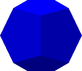
The lights are defined as shown above, and the camera looks straight down the Z axis. Notice that most of the visible faces are a different shade because each face is at a different angle to the light source. The horizontal and vertical scroll bars at the edges of the window let you scroll it. Faces on the bottom and rear are darker and not distinct because they're only illuminated by ambient light.
In this XAML file, each of the 12 pentagons that make up the dodecahedron are defined with its own set of six Point3D objects — one point for the center of the pentagon and five points for the five vertices. In the file, the Positions collection lists the six Point3D objects for each pentagon on a separate line. There are 12 lines of data for the 12 pentagons and a total of 72 Point3D objects in the Positions collection. Obviously, there are many duplicates points, because a dodecahedron has only 20 vertices total.
The TriangleIndices property lists the indices for the 12 pentagons each on a separate line. The first pentagon refers only to indices of 0 through 5 in the Positions collection; the second refers to indices of 6 through 11, and so forth. There are a total of 60 triangles in this figure: 5 for each of the 12 pentagon faces. (I am aware that the dodecahedron can be defined with only three triangles per face, but I wanted to take a more symmetric approach in this exercise.)
The Dodecahedron-SharedVertices.xaml file takes a different approach. The Positions collection has only 32 points — 12 for the centers of the 12 faces of the figure, and 20 for the 20 vertices. In the file, the TriangleIndices lists the indices for the six triangles of each pentagon face on a separate line, but vertices are shared among faces.
Not only is the MeshGeometry3D defined quite differently in the second file, but the result is quite different as well:
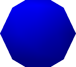
Were it not for the silhouette, you might think the surface were rounded like a ball. This is the effect of the default calculation of normals. If you don't supply a Normals property (which is a collection of Vector3D objects in one-to-one correspondence with the Positions collection) then normals are calculated for you. At each vertex in the figure, all the triangles that meet at that vertex are taken into account. Each of these triangles has a normal vector (which is a vector perpendicular to the face of the triangle), and an average is taken. That's the normal used to calculate reflected light at the vertex. Within each triangle, the amount of reflected light is interpolated from the normal vectors at the three vertices. In the center of each pentagon, five triangles meet at one point, but these five triangles lie in the same plane, so the normal vector at the vertex is the same as the normal to that plane. At the vertices of each pentagon, however, three triangles meet at an angle, and the normal vertex is the average of the three triangle normals.
This smoothing effect might be highly desirable if you're actually trying to approximate a curved surface. But if you want to render a polyhedron with flat faces, it's a total disaster!
And yet, the instinct of any prudent programmer is to minimize the number of points in the Positions collection and avoid redundancy. For rendering flat surfaces, it simply doesn't work that way. You need those duplicates. Don't worry about performance: My understanding is that the rendering process is triangle-driven rather than Positions driven; duplicates in the Positions collection have zero effect on performance.
On the other hand, if you're trying to render something with curved surfaces, then the default calculated normals might be sufficient, or they might not be exactly what you want, in which case you can supply your own.
For example, suppose you defined your dodecahedron as in the first example, and you later decided you wanted all the edges to be smoothed out. The dodecahedron is centered around the origin, so a little reflection convinces you that at each vertex, the normal should be equal to the point of that vertex. Take the Dodecahedron-DiscreteVertices.xaml file, select the whole Positions attribute, copy it within the MeshGeometry3D element and change the duplicate Positions attribute name to Normals. Now the file displays the same image as Dodecahedron-SharedVertices.xaml
However, there is no Normals property you can add to the Dodecahedron-SharedVertices.xaml file to get flat faces. The Normals collection is in a one-to-one correspondence with the Positions collection, and each vertex in this Positions collection is shared among three faces, so the area around that vertex is going to be illuminated the same regardless what you set the normal to.
The general rule is this: If you're defining a polyhedron with flat faces, use a separate set of vertices for each face, and don't forget to use DirectionalLight. If you're defining curved surfaces and want smoother transitions between the faces, by all means share vertices among the faces and let WPF 3D calculate normals.
In some cases, you'll want to supply your own Normals collection if WPF 3D isn't doing what you want. I've been working on a class that generates mesh geometries for a sphere. I wanted to be able to generate subsets of the sphere based on ranges of longitude and latitude. Yet, when I assembled a total sphere from subsets of the sphere, there were discontinuities at the seams. The problem was that the default normals at the edges of these parts of the sphere weren't being calculated correctly. When I supplied an explicit Normals collection based on a vector from the center of the sphere, the seams disappeared.
Let me conclude by offering a winter solstice gift — Dodecahedron-Animated.xaml, which displays a revolving dodecahedron with semi-transparent faces. Don't make it too large or it'll be a bit jerky.
Happy holidays!