Non-Affine Transforms in 2D?
August 25, 2007
Roscoe, N.Y.
A recent query on the MSDN Forum for WPF asked if it's possible to apply a non-affine transform to two-dimensional graphics. The simple answer is No. The 3×3 Matrix structure in the System.Windows.Media namespace does not allow setting the third column of the matrix required for non-affine transforms.
However, non-affine transforms are allowed in WPF 3D and, indeed, you might be able to get the effect you want without getting involved with transforms at all.
The two programs presented here both display a photo of myself in a square. Using the mouse, you can grab any one of the corners and drag it. You must click within the image! The nearest corner will jump to the mouse position and then you can drag the corner somewhere else. As you drag a corner, the other corners remain fixed. Here's the first version:
This is the simple approach: It uses WPF 3D to display a square on the XY plane. The 3D coordinates defined in the Positions collection of the MeshGeometry3D are (0, 0, 0), (0, 1, 0), (1, 0, 0), and (1, 1, 0). Whenever the image is clicked or dragged, the program gets the two-dimensional mouse point, converts it to 3D coordinates (with a simple method that only works with OrthographicCamera pointed straight back along the Z axis), and sets the proper item in the Positions collection. Here's the source code.
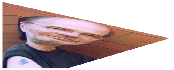
The problem with this technique is that the image is divided into two triangles, one on the lower left and the other on the upper right, and if you drag the bottom-left or top-right corner, only half the image is stretched, like this:

You can practically see the diagonal from the upper-left corner to the lower-right. Nothing below that diagonal is distorted.
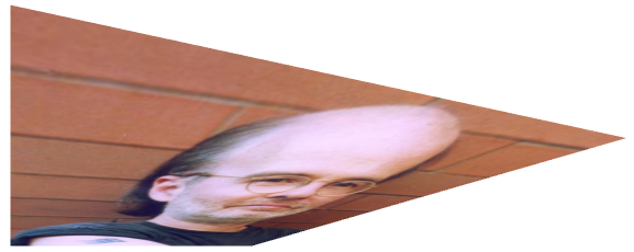
Perhaps a better approach is to apply an actual non-affine transform to the GeometryModel3D. This is done in the following program:
Yes, you can easily drag a corner to a place where the transform breaks down and the image flips over in strange ways. But, as you can see, whenever any corner is dragged, the entire image is affected:

Here's the source code for this second version. For the theoretical analysis that follows, I'll be assuming that we're just working with two dimensions. Converting to a flat surface in three dimensions where Z equals 0 is trivial.
The transform we want produces the following mappings (and I hope you're seeing arrows between the pairs of points):
-
(0, 0) → (x0, y0)
(0, 1) → (x1, y1)
(1, 0) → (x2, y2)
(1, 1) → (x3, y3)
The coordinates on the left of each line are the original coordinates of the corners of the image; the coordinates on the right are the four points we want for those corners. In general, this is a non-affine transform between it maps a square to an arbitrary quadrilateral. Affine transforms always map squares to parallelograms. The transform we desire will be much easier to derive if we break it down into two transforms:
-
(0, 0) → (0, 0) → (x0, y0)
(0, 1) → (0, 1) → (x1, y1)
(1, 0) → (1, 0) → (x2, y2)
(1, 1) → (a, b) → (x3, y3)
The first transform is obviously a non-affine transform that I'll call B. The second transform is something that I'll force to be an affine transform called A (for "affine"). The composite transform is B×A. The task here is to derive the two transforms plus the point (a, b). Let's derive the affine transform first.
An affine transform always maps a square to a parallelogram, so it is completely determined by the mappings of three points. I'll use the first three in the list:
-
(0, 0) → (x0, y0)
(0, 1) → (x1, y1)
(1, 0) → (x2, y2)
A 3×3 affine matrix can be represented like this (using the property names of the Matrix structure):
| M11 | M12 | 0 |
| M21 | M22 | 0 |
| OffsetX | OffsetY | 1 |
The transform formulas are:
-
x' = M11•x + M21•y + OffsetX
y' = M12•x + M22•y + OffsetY
It is easy to apply the transform to the points (0, 0), (0, 1), and (1, 0), and solve for the elements of the matrix:
-
M11 = x2 – x0
M12 = y2 – y0
M21 = x1 – x0
M22 = y1 – y0
OffsetX = x0
OffsetY = y0
It's not necessary to know this, but the fourth point of the square, which is (1, 1), is mapped to (M11 + M21 + OffsetX, M12 + M22 + OffsetY), which is the fourth point of the parallelogram. But we're not actually concerned with this point in this exercise. Instead, we want this affine transform to map a point (a, b) to the point (x3, y3). What is this point (a, b)? If we apply the affine transform to (a, b) and solve for a and b, we get:
-
a = (M22•x3 – M21•y3 + M21•OffsetY – M22•OffsetX) / (M11•M22 – M12•M21)
b = (M11•y3 – M12•x3 + M12•OffsetX – M11•OffsetY) / (M11•M22 – M12•M21)
Now let's take a shot at the non-affine transform, which needs to yield the following mappings:
-
(0, 0) → (0, 0)
(0, 1) → (0, 1)
(1, 0) → (1, 0)
(1, 1) → (a, b)
The generalized non-affine transform (using property names that are not defined in the Matrix structure) is:
| M11 | M12 | M13 |
| M21 | M22 | M23 |
| OffsetX | OffsetY | M33 |
And the transform formulas are:
-
x' = (M11•x + M21•y + OffsetX) / (M13•x + M23•y + M33)
y' = (M12•x + M22•y + OffsetY) / (M13•x + M23•y + M33)
The point (0, 0) is mapped to (0, 0), which tells us that OffsetX and OffsetY are zero, and M33 is non-zero. Let's go out on a limb and say that M33 is 1.
The point (0, 1) is mapped to (0, 1), which tells us that M21 is zero and M23 = M22 – 1.
The point (1, 0) is mapped to (1, 0), which tells us that M12 is zero and M13 = M11 – 1.
The point (1, 1) is mapped to (a, b), which requires a bit of algebra to derive the following:
-
M11 = a / (a + b – 1)
M22 = b / (a + b – 1)
The a and b values have already been calculated in connection with the affine transform.
The derivations of the affine matrix A and the non-affine matrix B are implemented in the CalculateNonAffineTransform method in the NonAffineImageTransform2.cs file. Of course, the method actually returns a Matrix3D object that is applied to the GeometryModel3D containing the image.
Using 3D graphics to implement a two-dimensional non-affine transform may sound a bit extravagant, but keep in mind that Viewport3D is a WPF element much like any other. You can easily mix it in with panels, TextBlock elements, controls, et cetera. In particular, it's very easy to determine the required size of the Viewport3D based on the size of figures viewed with OrthographicCamera, and to convert between the two coordinate systems.

|
Buy my book and we'll both be happy! | ||
| Amazon.com | BookSense.com | quantumbooks | |
| Barnes & Noble | Amazon Canada | Amazon UK | |
| Amazon Français | Amazon Deutsch | Amazon Japan | |