The Petzold.Media3D Library: The "Wire" Classes
August 31, 2007
Roscoe, N.Y.
As Eric Sink pointed out recently, "WPF 3D doesn't know how to draw lines.". Fortunately, the WPF 3D team at Microsoft has made available the 3DTools library that includes the ScreenSpaceLines3D class that derives from ModelVisual3D and draws lines in a 3D scene. The "screen space" in the name of this class indicates that you specify the thickness of the lines in terms of device-independent units, which are 1/96th inch and hence often pixels.
What's really nice is that the source code to ScreenSpaceLines3D is also available so you can see the clever techniques at work to make this happen: Basically, each line is a pair of triangles arranged in a long thin rectangle. While you specify the begin point and end point of this "line" in 3D coordinates, the ScreenSpaceLines3D class must determine the thickness of this "line" at each end so that after the various transforms have been applied to it (including the camera transforms — see Chapter 7 of my book 3D Programming for Windows) it ends up on the screen with a uniform thickness with a surface that is always oriented perpendicularly to the viewer.
This job requires that ScreenSpaceLines3D know about all the transforms that are applied to the visual because it must invert the transform chain to determine the dimensions and orientation of the line that it renders. What makes this job particularly tricky is that these transforms can be animated. For that reason, ScreenSpaceLines3D installs a handler for the CompositionTarget.Rendering event, and walks the parent/child chain up to Viewport3D on each vertical retrace of the video display. As Eric notes, this is a problem.
I spent a lot of time studying ScreenSpaceLines3D because I knew I wanted to implement something similar in my own Petzold.Media3D library (available here). At one point I derived from Viewport3D specifically to provide support for my "wire" classes (as I began thinking of them), but I eventually abandoned that approach.
Instead, my abstract WireBase class installs a handler for CompositionTarget.Rendering but it does so from a static constructor, so regardless how many WireBase objects you have, there's only one call to this handler per vertical retrace. Each instance of WireBase puts itself into a static collection that the CompositionTarget.Rendering handler enumerates for each call, at that point essentially performing the same logic as ScreenSpaceLines3D. However, if a particular WireBase instance discovers that its chain of visual parents no longer ends in a Window object, then it removes itself from this collection and is abandoned. This is how I hope my implementation is a little less insane than ScreenSpaceLines3D.
I had decided that I would be using XAML files to create all the illustrations in my book. Many of the illustrations were created from 400 DPI bitmaps that I generated from XamlCruncher 2.0. At that resolution, ScreenSpaceLines3D had some limitiations I simply couldn't tolerate. Not only did I need to shamelessly copy the technique of ScreenSpaceLines3D but I had to enhance it.
The "wire" classes I eventually created for the Petzold.Media3D begin with WireBase and are shown here roughly in increasing levels of complexity:
-
Object
DispatcherObject
DependencyObject
Visual3D
ModelVisual3D
WireBase
WireLine
WireLines
WirePolyline
WirePath
WireText
Axes
For me, the most serious problem with ScreenSpaceLines3D was the line joins. Here's a ScreenSpaceLines3D element with a width of 40 device-independent units:
-
<tools:ScreenSpaceLines3D
Points="-1 0 0, 0 0.5 0, 0 0.5 0, 0.5 0 0"
Thickness="40" Color="Blue" />
In ScreenSpaceLines3D you set the Points property to an even number of Point3D objects; each pair of points define one line. And here's what it looks like:

It's obviously two lines rather than a connected line. The class in the Petzold.Media3D library that's closest in syntax to ScreenSpaceLines3D is WireLines except the property is named Lines rather than Points:
-
<cp:WireLines Lines="-1 0 0, 0 0.5 0, 0 0.5 0, 0.5 0 0"
Thickness="40" Color="Blue" />
The image produced by that markup is the same as the ScreenSpaceLines3D example. However, I've also provided a property in WireBase named Rounding of type int that lets you specify the number of little pie slices used to approximate the rounding of the ends of each line:
-
<cp:WireLines Lines="-1 0 0, 0 0.5 0, 0 0.5 0, 0.5 0 0"
Thickness="40" Color="Blue" Rounding="10" />
And now the lines are rendered like this:

You can alternatively use the WirePolyline class and just specify the three points that make up this particular figure:
-
<cp:WirePolyline Points="-1 0 0, 0 0.5 0, 0.5 0 0"
Thickness="40" Color="Blue"
Rounding="10" />
Or, to draw a single straight line, you can use WireLine and set the Point1 and Point2 properties. The WireBase class also defines ArrowEnds, ArrowLength, and ArrowAngle properties to draw arrows at the end of the line (handy for symbolizing vectors in 3D space.)
Similar to the WPF 2D Path class, my WirePath class has a Data property of type PathGeometry3D, and if you check the Paths directory of the Petzold.Media3D source code, you'll find that my PathGeometry3D class defines a Figures property of type PathFigure3DCollection, and PathFigure3D defines a StartPoint property and a Segments property of type PathSegment3DCollection, and PathSegment3D is parent to the four classes LineSegment3D, PolyLineSegment3D, BezierSegment3D, and PolyBezierSegment3D. In other words, I've tried to duplicate the 2D path geometry classes in 3D. (What I didn't get around to doing was a PathGeometry3DConverter that would let you specify a whole path as an encoded text string, but it's high on my to-do list.)
For example, these classes allowed me to create the following XAML file for a figure in Chapter 6 of 3D Programming for Windows:
You can run that XAML file in XamlCruncher 2.0 if you have the Petzold.Media3D library loaded, or you can just run an XBAP created from the XAML file:
It looks like this:
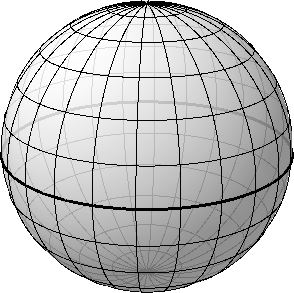
It looks better in the book (page 240) because that image was created at 400 DPI rather than 96 DPI as it is here. (It also looks better on the screen with a Tier 2 graphics board because you get anti-aliasing. You don't get anti-aliasing when you're rendering 3D scenes on bitmaps.) All the lines of longitude and latitude are WirePath objects, but inside is a sphere colored with a translucent brush to make the lines around the back a little less dark.
The WireText text class is based around the polylines from the ancient Windows plotter fonts. You set the Font property to a member of the Font enumeration (Modern, Roman, or Script) and FontSize to an approximate character height in 3D units. Set the Origin property to a Point3D where the text is to begin, and HorizontalAlignment (default is Left) and VerticalAlignment (default is Top) to indicate the meaning of that origin. You'll also need to set two vectors: BaselineDirection (default is (1, 0, 0)) and UpDirection (default is (0, 1, 0)). The cross product of BaselineDirection and UpDirection indicates the direction from which the text appears normal. Set the Text property to the text you wish to display.
The size of the text characters will get smaller as the text recedes to the background, but the actual strokes that make up the characters will not. Those are governed by the Thickness property defined by WireBase.
Finally, the Axes class combines lines and text to display the 3D coordinate axes:
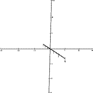
Of course, several properties let you set the Extent of the axes (the default is 3), whether it will ShowNumbers, the length of LargeTick and SmallTick, and you can even replace the Labels from X, Y, and Z to something else, such as shown on page 317 of my book.
NOTE: For reasons discussed in paragraph 5, these Wire classes will not work when you're hosting 3D in Windows Forms, or when you're trying to print a 3D scene. To make it work, try replacing the static OnRendering method in WireBase with the following:
static void OnRendering(object sender, EventArgs args)
{
foreach (WireBaseAndUltimateParent wirebaseAndParent in listWireBases)
{
WireBase wirebase = wirebaseAndParent.wirebase;
wirebase.OnRendering();
}
}
|
Buy my book and we'll both be happy! | ||
| Amazon.com | BookSense.com | quantumbooks | |
| Barnes & Noble | Amazon Canada | Amazon UK | |
| Amazon Français | Amazon Deutsch | Amazon Japan | |